
Cavity assisted spectroscopy methods
Cavity assisted spectroscopy methods are increasingly common techniques for making very sensitive optical extinction measurements. Most of the research with cavity assisted systems has concentrated on gas-phase samples, but recently there have been several studies of optical extinction by aerosol particles, ions and clusters. At the IMK-AAF we facilitate different cavity assisted spectrometers with several kilometers optical light path to measure extinction of extremely diluted samples.
Cavity assisted extinction spectrometers comprise an optical cavity, built of at least two highly reflective mirrors in which photons propagate for a prolonged time. A virtually long optical light path for the extinction measurement is provided by such a cavity in a comparatively small setup (<1 m). The intrinsic loss of the resonator can be measured by the lifetime of the photons inside. In the case of a cavity pumped by light pulses, the decay time of the light leaking out of the cavity yields the mean photon lifetime. This technique is named cavity ring-down spectroscopy (CRDS). If the cavity is pumped by a continuous light source, the light leaking out of the continuously pumped cavity yields the mean photon lifetime. As this technique is more equal to classic absorption spectroscopy, enhanced by a long optical light path, it is named cavity enhanced absorption spectroscopy (CEAS).
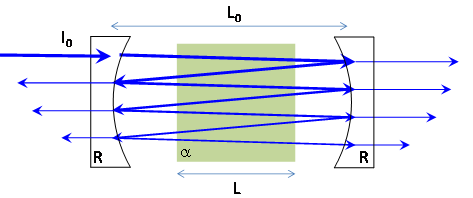
Figure 1: Scheme of a cavity assisted extinction spectrometer with two mirrors with high reflectivity R. A small fraction of light shining on the entrance mirror is transmitted into the resonator. Once inside the cavity, the light Iin propagates the distance L0 to the second (exit) mirror, were the fraction Iin• R is reflected and a small fraction Iin• T is transmitted by the highly reflective mirror surface. The remaining fraction of light inside the cavity propagates back to the entrance mirror, where the process recurs until no light is left inside the cavity. If an absorber with the absorption coefficient α is inside the resonator, the light intensity inside the cavity is reduced by α • L with each traverse. Depending whether the input intensity is pulsed or continuous, the observer looking at the exit mirror senses intensity decay or continuous absolute intensity related to the losses inside the cavity, respectively.
The length of the light path within the cavity is a function of the mirror reflectivity. Higher reflectivity results in longer paths. In order to approach the kilometer range mirror reflectivities needs to be larger than 99.9%. In this case mirror transmission can obviously not be higher than 0.01% and will typically be even smaller than that, as mirrors with 99.9% reflectivity are rather the lower limit of what can sensibly be used for cavity setups. A low mirror transmission means, that the introduction of light into the cavity is highly suppressed and most of the incident light will be reflected and never enter the cavity. Because of this, the signal strength transmitted by the resonator decreases as the light path increases.
To overcome this problem optical-feedback techniques can be applied. Instead of the classical two mirror setup, e.g. a V-shaped cavity consisting of three mirrors pumped by a laser diode can be used. This special setup has the advantage of geometrically separating the transmitted and the reflected beam on the incident mirror. As a result only light from inside the cavity is reflected backwards into the laser diode. As resonators are highly selective frequency filters, this optical feedback can be exploited to frequency-lock the laser radiation to cavity resonances. Furthermore, up to 25% of the laser light is transmitted through the resonator making the signal strength independent of the optical path length.
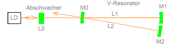
Figure 2: Schematic of a V-Shaped cavity. Light from the laser diode (LD) passes an attenuator (L0) and then reaches the resonators incident mirror (M0). The part of light not passing M0 is reflected but not into the laser diode, only light from within the resonator serves for feedback purposes. The attenuator regulates the feedback strength.
We use this approach to measure extremly small water vapour concentrations with the REWAS (Resonator Enhanced Water Absorption Spectrometer) instrument an optical feedback cavity enhanced absorption spectrometer (OF-CEAS). In this instrument OF-CEAS is used to determine a water absorption line profile and combined with intermittent CRDS measurements to determine the optical path length.
The TRAPS apparatus (Trapped Reactive Atmospheric Particle Spectrometer) facilitates an incoherent CEAS/CRDS spectrometer confining an ion-trap in an ultry high vacuum system for the determination of optical properties of free nanoparticles of atmospheric relevance. Atmospheric aerosols absorb and reflect solar radiation which causes surface cooling and heating of the atmosphere. The interaction between aerosols and radiation depends on their complex index of refraction, which is related to the particles’ chemical composition. Looking at primary particles in the nanometer range, optical properties become strongly dependent on size and chemical composition.
Information on a cavity enhanced system with optical feedback are given here (OF-CEAS):
Optical feedback cavity enhanced absorption spectroscopy: effective adjustment of the feedback-phase, J. C. Habig, J. Nadolny, J. Meinen, H. Saathoff and T. Leisner, Applied Physics B-Lasers and Optics, 106 (2), 491-499 (2012)
Information on a cavity enhanced DOAS system to measure NO3 radicals are given here (CRDS):
Using a high finesse optical resonator to provide a long light path for differential optical absorption spectroscopy: CE-DOAS, J. Meinen J. Thieser, U. Platt, and T. Leisner Atmos. Chem. Phys. 10, 3901-3914 (2010)
Broadband Cavity Enhanced Differential Optical Absorption Spectroscopy (CE-DOAS) – applicability and correctionsAtmos. Meas. Tech., 2, 713-723, 2009